Overview
Active Noise Cancellation (ANC) and Environmental Noise Cancellation (ENC) are different noise reduction technologies. Active noise cancellation cancels out ambient noise on your end, ensuring voice you heard is not disturbed by a noisy environment. Environmental noise cancellation, on the other hand, uses algorithms to eliminate ambient noise from the sound you send, allowing the other party to hear you clearly. Using headphones with ENC technology, even if you are on a noisy roadside, on a speeding motorcycle, or in a moving car with the windows open, the recipient can still hear you clearly. In short, active noise cancellation ensures you hear the other party clearly, while environmental noise cancellation ensures the other party hears you clearly.
There are three main technologies for ENC:
- Adaptive Filtering Technique
- Beamforming Technology
- Bone Conduction
These three technologies aren’t actually that new. Our phones generally have two microphones (one near the charging port, the other near the camera), which have been silently helping us with noise reduction during calls for years (which is why we sometimes turn off our headphones and use our phones directly when we’re worried about not being able to speak clearly). The essence of ascending bone conduction technology is to transmit call content by collecting vibration signals from the cheeks or vocal cords. Since the medium for transmitting ambient noise is air, directly collecting vibrations from the cheeks or vocal cords using an accelerometer avoids transmitting ambient noise into the transmission device. This technology has wide applications in the military; for example, it can be used to make calls from inside moving tanks or helicopters.
The current design of TWS earbuds has accelerated the application of these three technologies in earphones. The golf club-like shape of TWS earbuds allows the dual microphones to be positioned further apart, improving the beamforming algorithm effect; the semi-in-ear design of TWS earbuds allows the vibration of the ear cartilage to be transmitted to the accelerometer more efficiently, and the ascending bone conduction can obtain a signal with a higher signal-to-noise ratio; at the same time, the advancement of Bluetooth chip computing power and power consumption allows these algorithms to run better within the chip.
This article mainly discusses the testing methods for ascending bone conduction technology .
First, based on the direction of signal transmission, bone conduction can be divided into ascending and descending bone conduction communication technologies.
- Ascending bone conduction is a design that improves call quality by capturing facial vibration signals, with the aim of enabling the recipient to hear your voice clearly.
- Descending bone conduction converts received sound signals into vibration signals of different frequencies, which are then transmitted to the brain via organs such as the skull, bony labyrinth, inner ear lymph, cochlea, and auditory center, with the aim of enabling you to clearly hear the speaker’s voice.
During a call, our own voice is the only effective signal that needs to be transmitted. However, there are often environmental noise signals in the call environment, which are generated by various noises such as machinery, wind, and people around us.
The essence of ascending bone conduction technology is to place an accelerometer chip inside the earphone to capture the vibration signal transmitted from the vocal cords to the cheeks, and transmit this effective signal as the content of the call. Since ambient noise needs to be transmitted to the microphone through the air, it will not be collected by the accelerometer, thus achieving the effect of filtering air conduction noise.
When we speak, in addition to the vibrations transmitted to our cheeks, the vibrations transmitted to the bridge of our nose are also quite strong. Therefore, ascending bone conduction technology can not only be used in the field of headphones, but also in smart wearable devices such as VR or AR to optimize call clarity.
MegaSig Bone Conduction Testing System
The test of ascending bone conduction communication technology can be divided into three parts:
- IQC (Incoming Chip Testing)
- Semi-finished product bone conduction testing
- Final product bone conduction testing
All three of the above tests are seamlessly compatible with MegaSig’s bone conduction testing system.
IQC (Incoming Chip Testing)
Incoming quality control (IQC) testing of wafers is crucial. Controlling and inspecting the quality of raw materials is the first quality control checkpoint before production. If defective products flow into the manufacturing process, the consequences can range from disassembling and replacing parts to scrapping the entire machine, resulting in considerable human and economic losses.
Incoming quality control (IQC) chip testing can be categorized into digital and analog formats based on signal type. Below, we will analyze the measurement principles using the architecture diagram.
The first type is IQC digital chip microphone testing system:
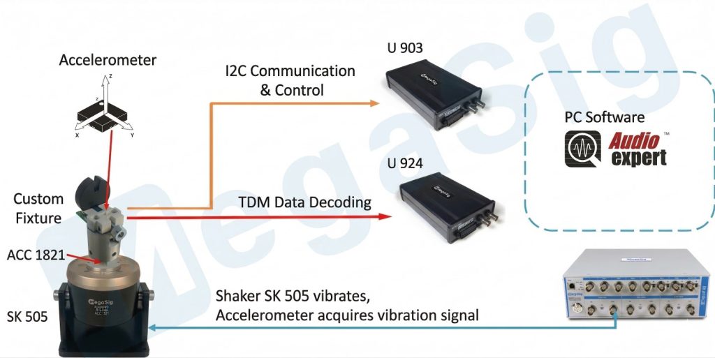
The analysis software AudioExpert sends a sweep signal to the exciter SK 505 to make it vibrate. After the IQC digital chip aligns with the pins of the customized fixture, it communicates with U 903 and demodulates the received vibration signal in digital TDM format to U 924 before transmitting it to the analysis software AudioExpert for analysis.
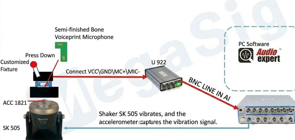
The second type is IQC analog chip microphone testing system:
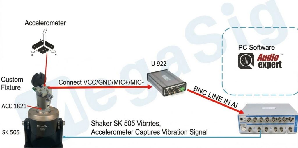
The AudioExpert software sends a sweep signal from the analyzer to the SK 505 vibrator to make it vibrate. The four points corresponding to the pins of the custom fixture are led out and connected to the U922. The signal is transmitted back to the analyzer via the U922 and then analyzed by the AudioExpert software.
Semi-finished Product Bone Conduction Testing
When attaching the accelerometer patch, poor contact may occur due to human error, such as cold solder joints or false solder joints, resulting in intermittent signal transmission. Therefore, a bone conduction test is required for the semi-finished product.
Similar to IQC chip incoming material testing, the bone conduction test for semi-finished products can be divided into digital format and analog format based on the signal type.
The first type is semi-finished prodcut bone conduction digital microphone testing system:
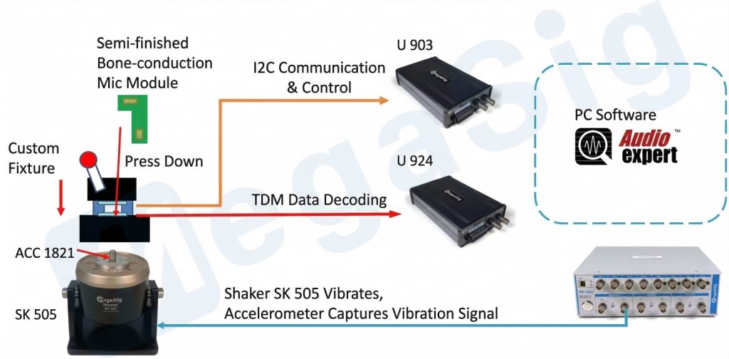
Since both tests are conducted via I2C communication and TDM format data demodulation, the overall testing logic can be referenced from the IQC digital chip microphone testing logic.
The second type is semi-finished product bone conduction analog microphone testing system:
The overall testing logic can be referenced from the IQC analog chip microphone testing logic.
Finished Product Bone Conduction Testing
After testing the incoming materials and the semi-finished products, the next step is to apply glue and assemble the headphones. Here, the accelerometer often does not work as expected because the position of the sensor deviates from the design position during assembly, or too much or too little glue is applied to the areas that need it. Therefore, after assembly, the finished product still needs to be tested.
The following is the system architecture diagram for testing finished product of bone conduction headphones:
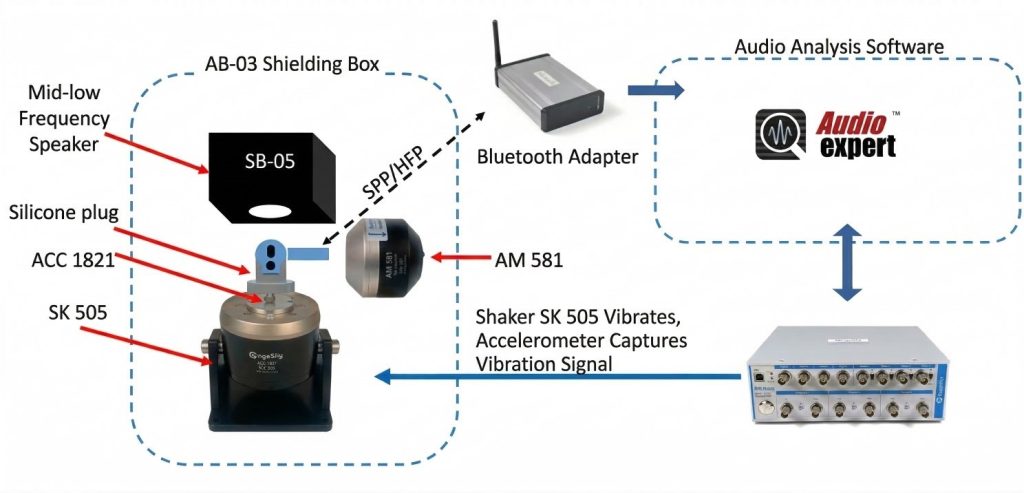
All finished products of bone conduction headphone are tested wirelessly. The AudioExpert analysis software sends a sweep signal from the analyzer to the SK 505 vibrator to make it vibrate. The internal accelerometer of the headphones receives the vibration signal, processes it internally, and then transmits it to the Bluetooth adapter via the SPP/HFP protocol. The Bluetooth adapter then transmits it back to the AudioExpert analysis software for analysis.
One point to note is that in finished product of bone conduction headphones, the bone conduction sensor usually coexists with other normal microphones. Therefore, additional hardware capable of testing normal microphones is also required, such as the SB 05 speaker and the AM 581 artificial mouthpiece.
System Configuration
- AudioExpert Basic Analysis Software
- PM6143 analyzer, 1 unit
- Bluetooth Adapter U982, 1 unit
- Electret and analog MEMS microphone power supply module U922, 1 unit
- U924 digital sequence I/O module, 1 unit
- I2C serial communication control box U903, 1 unit
- Artificial mouthpiece AM581, 1 unit
- SK506 vibration table, 1 unit
- ACC1821-SxLx single-axis accelerometer, 1 unit
- Computer host, 1 unit
- Display, 1 unit
- Silent enclosure AB04, 1 unit
- Work cabinet D04, 1 unit
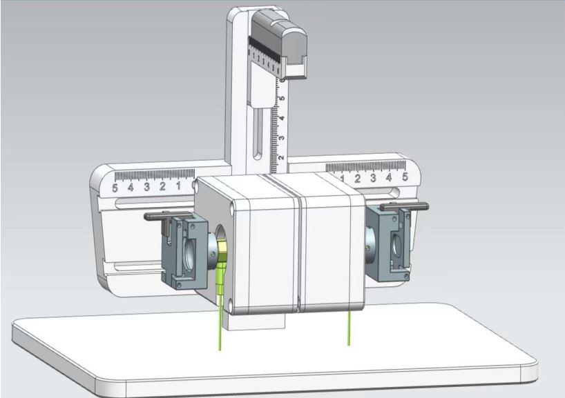
- Customized fixture (airtight), 1 unit
- Customized test sequence, 1 unit