I. Overview
As manufacturers of devices with digital MEMS microphones (such as laptops, webcams, mobile phones, IP cameras, etc.), we often need to test the performance of microphone modules. To convert the digital signals generated by the MEMS microphone into analog signals and transmit them to an analyzer for acoustic analysis, a converter board is typically used for Pulse Density Demodulation (PDM). However, in practice, when evaluating different microphone modules, the same PDM converter board is not always used for testing. This means that the performance of the PDM converter board can become a variable in the test results, making it difficult for developers to definitively say whether performance differences stem from design variations or differences in the PDM converter board, even if they have collected test data from multiple microphone modules they designed.
To address the aforementioned issues, MegaSig launched the U920A PDM signal converter.
The U920A features dual-channel output and uses an independent demodulation chip, resulting in lower noise floor and faster hardware response. It supports voltage and clock adjustment (serial port programmable). The output uses a BNC interface and provides analog signals, making it easy to use with various analyzers and sound cards.
II. Specifications
| Overall parameters | |
| PDM conversion channel number | 2 |
| Input Interface | EDGRM-3.81-8P |
| Output Interface | BNC |
| Input/output conversion ratio | 1%FS=5mVrms, 10%FS=50mVrms, 20%FS=100mVrms, 50%FS=250mVrms, 100%FS=500mVrms |
| Supported microphone voltage (DC) | 1.2V, 1.5V, 1.8V, 3.3V |
| Supported microphone clock speeds (Hz) | 768K, 800K, 812.5K, 1.2M, 1.536M, 2.4M, 3.072M, 3.25M |
| Product dimensions (mm) | 140*96*33 |
| Output mode | Single-ended output |
| Net weight (kg) | 0.35 |
| Packaging dimensions (mm ) | 250*165*65 |
| Packaging weight (kg) | 0.52 |
| Operating temperature | -20℃ to 50℃ |
| Operating voltage | DC 5V (USB-B) |
| Typical power consumption | 1 watt |
| Full load power consumption | 3 watts |
| Communication methods | Serial communication |
PDM demodulation channel characteristic parameters
| PDM demodulation channel characteristic parameters | |
| Sampling rate range (Hz) | 12,000–50,780 |
| Sampling rate interpolation | x64 |
Channel asynchronous mode single point parameters
| Idle channel noise (uVrms) | ||
| Sampling rate | fs=48kS/s | |
| Typical value | ≤14 | |
| Maximum value | 15 | |
| Test conditions: [1] Output source: APx525-PDM module, acquisition end: APx525-AI module (UNBAL) [2] U 920A voltage setting 3.3V; clock setting 3.072MHz; asynchronous mode [3] Output source signal output: -144dBFS, acquisition end filter setting: no weighting, no EQ, 10Hz high-pass filter | ||
| Total Harmonic Distortion (THD) (dB) | ||
| Sampling rate | fs=48kS/s | |
| Typical value | ≤-79 | |
| Maximum value | -78 | |
| Test conditions: [1] Output source: APx525-PDM module, acquisition end: APx525-AI module (UNBAL) [2] U 920A voltage setting 3.3V; clock setting 3.072MHz; asynchronous mode [3] Output source signal output: -144dBFS, acquisition end filter setting: no weighting, no EQ, 10Hz high-pass filter | ||
| Total Harmonic Distortion (THD+N) (dB) | ||
| Sampling rate | fs=48kS/s | |
| Typical value | ≤-79 | |
| Maximum value | -77 | |
| Test conditions: [1] Output source: APx525-PDM module, acquisition end: APx525-AI module (UNBAL) [2] U 920A voltage setting 3.3V; clock setting 3.072MHz; asynchronous mode [3] Output source signal output: -10dBFS 1kHz, acquisition end filter setting: no weighting, no EQ, 10Hz high-pass filter | ||
| Signal-to-noise ratio (SNR) (dB) | ||
| Sampling rate | fs=48kS/s | |
| Typical value | ≥94 | |
| Minimum value | 93 | |
| Test conditions: [1] Output source: APx525-PDM module, acquisition end: APx525-AI module (UNBAL) [2] U 920A voltage setting 3.3V; clock setting 3.072MHz; asynchronous mode [3] Output source signal output: 0dBFS 1kHz, acquisition end filter setting: no weighting, no EQ, 10Hz high-pass filter | ||
Channel synchronization mode single point parameters
| Idle channel noise (µVrms) | ||
| Sampling rate | fs=48kS/s | |
| Typical value | ≤14 | |
| Maximum value | 15 | |
| Test conditions: [1] Output source: APx525-PDM module, acquisition end: APx525-AI module (UNBAL) [2] U 920A voltage setting 3.3V; clock setting 3.072MHz; asynchronous mode [3] Output source signal output: -144dBFS, acquisition end filter setting: no weighting, no EQ, 10Hz high-pass filter | ||
| Total Harmonic Distortion (THD) (dB) | ||
| Sampling rate | fs=48kS/s | |
| Typical value | ≤-78 | |
| Maximum value | -77 | |
| Test conditions: [1] Output source: APx525-PDM module, acquisition end: APx525-AI module (UNBAL) [2] U 920A voltage setting 3.3V; clock setting 3.072MHz; asynchronous mode [3] Output source signal output: -144dBFS, acquisition end filter setting: no weighting, no EQ, 10Hz high-pass filter | ||
| Total Harmonic Distortion (THD+N) (dB) | ||
| Sampling rate | fs=48kS/s | |
| Typical value | ≤-77 | |
| Maximum value | -76 | |
| Test conditions: [1] Output source: APx525-PDM module, acquisition end: APx525-AI module (UNBAL) [2] U 920A voltage setting 3.3V; clock setting 3.072MHz; asynchronous mode [3] Output source signal output: -10dBFS 1kHz, acquisition end filter setting: no weighting, no EQ, 10Hz high-pass filter | ||
| Signal-to-noise ratio (SNR) (dB) | ||
| Sampling rate | fs=48kS/s | |
| Typical value | ≥94 | |
| Minimum value | 93 | |
| Test conditions: [1] Output source: APx525-PDM module, acquisition end: APx525-AI module (UNBAL) [2] U 920A voltage setting 3.3V; clock setting 3.072MHz; asynchronous mode [3] Output source signal output: 0dBFS 1kHz, acquisition end filter setting: no weighting, no EQ, 10Hz high-pass filter | ||
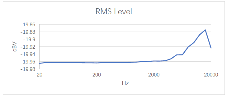
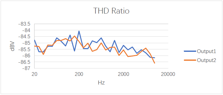
Channel Asynchronous Mode Frequency Sweep Parameters
| Frequency Response | ||
| Test conditions: [1] Output source: APx525-PDM module, acquisition end: APx525-AI module (UNBAL) [2] U 920A voltage setting 3.3V; clock setting 3.072MHz; asynchronous mode [3] Output source signal output: 0dBFS 1kHz, acquisition end filter setting: no weighting, no EQ, 10Hz high-pass filter |
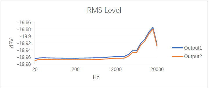
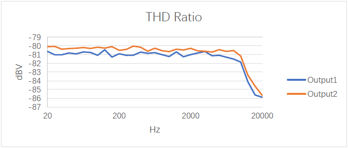
Channel synchronization mode frequency sweep parameters
| Frequency Response | ||
| Test conditions: [1] Output source: APx525-PDM module, acquisition end: APx525-AI module (UNBAL) [2] U 920A voltage setting 3.3V; clock setting 3.072MHz; synchronization mode [3] Output source signal output: 0dBFS 1kHz, acquisition end filter setting: no weighting, no EQ, 10Hz high-pass filter |
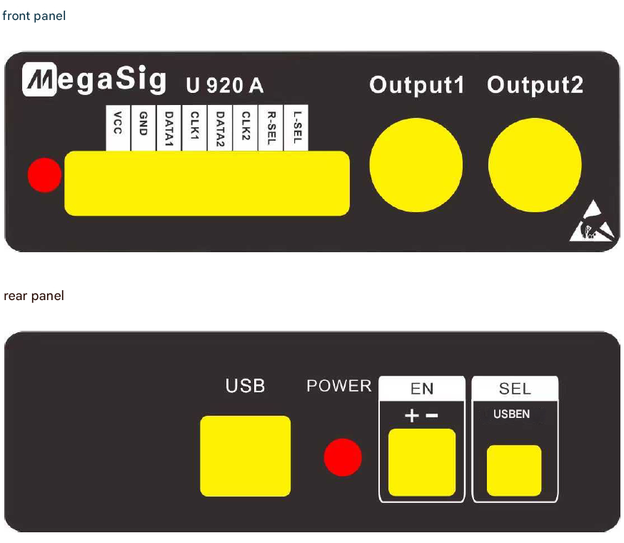
III. Front and rear panels